What it Takes to Fly an Autogyro

Most people–heck, even most pilots–don’t know what a gyroplane or autogyro is. To the untrained eye, it looks like a helicopter. But it is neither a helicopter nor is it a traditional airplane. Rather it is an aircraft type that uses a spinning rotor as its wing, much like a helicopter. But like an airplane, it uses a fairly conventional propeller to drive it forward through the air. The big difference between an autogyro and a helicopter is that the lift-providing rotor is not driven by the aircraft’s engine. Rather it rotates on its own, following the effect known as “autorotation.” As a result, there is no tail rotor and this is perhaps the fastest way to tell an autogyro from a helicopter. Most modern gyroplanes use a “pusher” propeller mounted behind the pilot and immediately in front of the tail assembly. This too, is an indicator that the craft in question is a gyro and not a helicopter.

Autogryo USA Cavalon, a side-by-side two-seater light-sport gyroplane powered by a Rotax 914 engine.

The big difference between the autogyro and a traditional airplane is that the autogyro doesn’t stall. That rotor-for-a-wing that spins on top continues to create lift even as forward airspeed drops to zero. And while a gyro cannot hover like a helicopter it can fly slower than most airplanes.

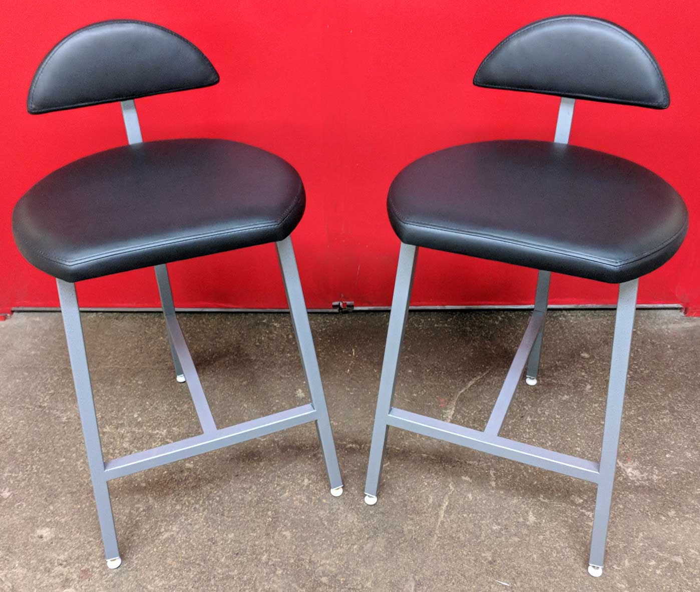
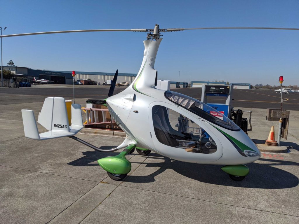
I remember hearing about autogyros when I was flying gliders back in the aughts. I would run across them in FAA guidelines, yet no one I asked seem to have a good explanation of what they were. I forgot about them until 2018, when I attended the Experimental Aircraft Association’s Oshkosh airshow. In February 2020, I got a chance to learn how to fly a gyroplane. Under the direct supervision of a Certified Flight Instructor, I flew the aircraft pictured above on 12 separate days, accumulating 23 hours of flight time. (This still qualifies me as a complete noobie, by the way.) This post includes a six-minute video showing one takeoff and landing at the end of day 11 of training. I am annotating it with a detailed description of the key things that I did to takeoff, land and fly this gyroplane. I offer this to inform those who might be interested in learning what is involved in flying a gyroplane and broadly how it differs from flying other types of aircraft. This is not an instructional video. You cannot learn to fly a gyroplane by watching this video or reading this webpage. No one should attempt to fly any aircraft without proper and detailed hands-on instruction and appropriate certification.

OK, here’s what this post includes:

  1. Control panel diagram with labels and explanations
  2. A point by point description of my actions through the video. (This description is more detailed and includes sections omitted from the one given on the Youtube page.)
  3. The actual video, embedded from YouTube.

#gyroplane #gyrocopter #Autogyro #AutogryroUSA

Instruments and Controls

Cavalon 425AG Cockpit Panel (See identification notes below.)

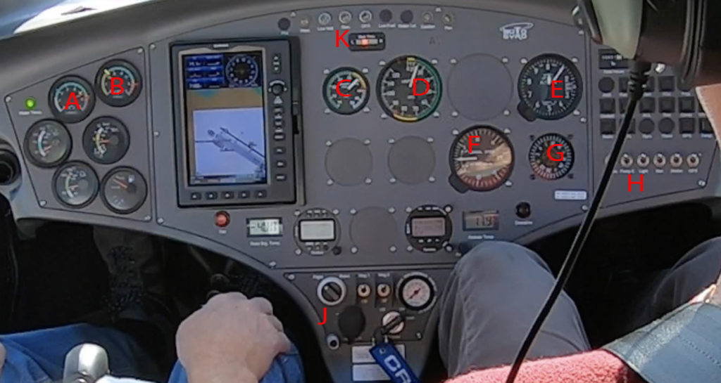
Example of an Autogyro USA Cavalon Instrument Panel (Due to owner preferences, not all are the same.)

A – Engine RPMs – green zone is 1,400 to 5,500 rpm. Mostly used during taxi, engine warm and rotor pre-rotation on the ground. 

B –  Rotor RPMs – yellow zone up to 220 RRPM, green above that to 550 RRPM. Generally in 300-400 range. 

C –  Engine Manifold Pressure – primary indication of engine power during takeoff and flight.

D – Airspeed indicator – First labeled number is 20 knots. Green arc from 16 to 70 kts. Red zone at 86 kts. (See endnote on safe airspeeds.)

E – Altimeter (showing elevation above sea level, 90 ft while on the ground at Petaluma airport)

F – Variometer – sink/climb in feet per minute. Level flight at 9 o’clock. 1st major hash @5(00) fpm up & down. Not very accurate <~200 fpm.

G – Compass showing heading

H – Electrical switches – second from left is “Pump 2” which generally only runs during takeoff and landing. “Light” is 3rd from left.

J – Rotor Brake – Shown in “Flight” or “free” position in this picture. Switched to “Brake” position to slow and stop the rotor after landing.

Right of the rotor brake are the two engine magneto switches then a pressure gauge for the rotor brake which has to be pumped up each time it is applied. Pump is actuated by the conical thumb switch (also used to adjust trim) on the top rear of the stick. 

K – Warning and indicator lights. (Top of panel.) The “Low voltage” light comes on at minimum idle speed on the ground.

The gauges below A and B are oil temperature and pressure, water temperature and then fuel gauge.

I do not yet have any experience with the installed avionix/navigation panel. 

Flight Controls

Each pilot has a stick which controls the attitude (pitch/angle/tilt) of the rotor on the top of the aircraft. The stick includes three buttons: a “push-to-talk” radio button on the front and activated by the index finger; a “rotor pre-rotator” button at the far front end of the thumb rest and activated by the thumb; and finally, a cone-shaped button on the top back portion which is also activated by the thumb. This cone-shaped button is used in flight to adjust trim and on the ground when the rotor brake is in “brake mode” to pump up the rotor brake.  

In the center console between the two seats are the “gas and brakes”—more appropriately known as the engine throttle and the wheel brake. 

The aircraft also has traditional pedals tied to the nose wheel and the rudder on the back half of the vertical stabilizer. Rudder controls are typically very lightly used in flight as the aircraft doesn’t seem to need much balancing in turns. The time they are most needed actually tends to be when adding or reducing power to counteract the engine-induced yaw.

Video Explanation:

This video shows two people in an Autogyro USA Cavalon gyroplane. The primary pilot (in this case a student pilot) sits on the right side and the secondary pilot (a gyroplane CFI) on the left. This is a takeoff to the pattern, returning to the same runway, which is 11 at Petaluma. 

Flight Sequence 

As the video begins, we are pulling on to the runway. The rotor brake has just been turned off, so the rotor is not turning.

At 0:05 I use the wheel brake to bring us to a stop and then adjust the throttle to 2000 rpm—just a bit above the normal idle speed—to begin the pre-takeoff process. At 0:09/0:10 I shift my thumb forward on the stick to activate the pre-rotator button. Throughout the pre-rotation sequence, my left hand is holding the wheel brake and also adjusting the throttle. 

It takes fully five seconds after the pre-rotator is applied before the rotor starts to turn—you’ll see the rotor shadow pass by for the first time at about 0:15. The pre-rotator puts quite a load on the engine and through this part of pre-rotation, I am closely watching the engine RPM gauge to ensure that rpms don’t drop below 1600 rpm. At 0:20, you’ll see me briefly lift my thumb from the pre-rotator button. This relieves the downward trend of engine rpms. Once the rotor starts spinning, engine rpms quickly return to pre-engagement level of 2000 rpm. Now I add throttle starting at about 0:28 and you’ll see from the rotor shadow that it spins faster and faster. I’m still looking left, but now at the rotor RPM gauge. When it reaches 200 rotor rpms, it is time to disengage the pre-rotator and initiate the takeoff roll. 

At 0:35, four important things happen in a specific sequence: 1) release pre-rotator button, 2) move stick to the fully back and centered position, 3) release the wheel brake and 4) advance the throttle to takeoff power. (Starting here, we rely on manifold pressure as the chief measure of engine output.)

Now it is time to pilot the aircraft! For a safe takeoff, we need to achieve two things: 1) a minimum of 220 rotor RPMs and 2) adequate airspeed to climb out. With the stick fully back, the rotor is tilted back and our take-off roll is forcing the greatest possible amount of air through the rotor. This increases the speed of the rotor at the same time that our forward speed increases. You can just make out the indicator needle on the rotor RPM gauge: it quickly passes the 220 minimum and by 0:49 or so, it passes 300. This is about when the nose starts to come off the ground. Ideally, we want to hold that nose wheel just off the ground and continue the runway roll as forward speed builds. (This is done by easing the stick forward just a bit.) I manage to maintain that attitude for about five seconds (which isn’t bad, I think!). At a speed of about 40 knots, the plane becomes airborne (0:56). At this point, we would still like to build more airspeed before we climb (see note on safe airspeed at the end of this description), so I push the throttle to full power to ensure that we won’t descend again and hold it close to the runway for a few more seconds. By 1:05, we reach 50 knots and we start to climb. Once airspeed climbs a bit more, I’ll pull the nose up a bit to achieve the “best climb” speed of ~55 kts and I’ll tweak the trim button on the back of the stick to help hold that attitude. You’ll see that that the variometer has jumped up to show a climb rate of 500 fpm and of course the ground falls away quickly. I am flying a gyroplane!

From here, we climb steadily. At 1:49 we past 500 feet of elevation and I pull back the throttle a bit to moderate the load on the engine but still keep us climbing. We will then turn left into the pattern. About 2:35 as I make another left hand turn onto the downwind leg of the pattern, you’ll notice the CFI grabbing the stick with his thumb and forefinger. He is doing this to activate the radio talk button and say something to the traffic in the area. (He laughs a few times a minute or two later—there was some joking going on amongst the pilots with each saying “Petaluma” in a silly way at the end of their traffic announcement. He also sometimes answers radio checks, questions from approaching pilots who are still out of sight of the airport, etc.)  Shortly after that turn at ~2:54, we are approaching the pattern altitude of 1000 feet, so I pull back on the throttle to stop climbing and adjust rotor attitude to keep us flying at 55 to 60 kts. 

Then at about 3:33, I pull back the throttle to begin our descent and soon start a left turn on to the base leg of the pattern. We turn base at about 700 feet altitude and final at about 500 feet of altitude. On most approaches, I’m about 100 feet higher at each of those points, but those altitudes are just fine. 

Once we are on final, I point the nose of the aircraft at the end of the runway and try to keep the end stripes in a fixed location in my windshield. I use stick to maintain airspeed in the 55 to 60 kts range and throttle to control our rate of descent. As we get to less than ten feet above the runway, I ease the stick back to raise the nose and slow our descent. This has the effect of also increasing the overall drag of the rotor, slowing us and causing us to descend further. At this point, I am trying to achieve a smooth descent that slows to nearly nothing as we touch down. (You’ll see the CFI place his hand near the stick at the final part there, just in case he needs to take any corrective action but, fortunately, he does not need to!)  

I find that the stick movement immediately after touchdown is the single most counterintuitive thing there is about flying a gyro. In every aircraft I’m familiar with, if you want the nose to go down, you move the stick forward. Commonly, that’s what you do after landing. Or maybe you hold steady with the nose still off the ground for a few seconds to bleed off some speed and then when it drops, you push the stick forward. Not so with the gyro.  When you move the stick forward after landing in a gyro it tilts the rotor forward which causes the plane to speed up and increases the lift being applied. Speeding down the runway and hopping back into the air are not what we want at this point. Furthermore, the stick forward move puts all the weight on that single front wheel which can react unpredictably and might cause the airplane to tip dangerously to either side. (I’ve been told that runway/taxiway incidents account for the vast majority of gyroplane accidents.) 

The RIGHT thing to do after landing, is to pull the stick to the rear-most position (pausing to let the nose settle if it comes off the ground along the way as happens in this case). Wtih that rear position the rotor is tilted all the way back, contributing maximum drag and minimum lift. As a result, speed bleeds off and the gyro quickly slows. 

This fully-back stick position is only held for a few seconds: just long enough to slow the gyro. It is important that as soon as the speed reaches that of a walk, the stick be pushed forward again—if not the rotor forces will actually start to pull the plane backwards. In this case I got distracted with turning onto the taxiway and didn’t get the stick forward fast enough to satisfy my instructor so he gives a helpful push on the stick to remind me. 

Once we are clear of the active runway, I stop the plane using the wheel brake (and set it so it won’t release). Then I activate the rotor brake and switch off pump 2 and lights to reduce electrical load. I forget to bump the engine speed up a bit to try to keep the “low voltage” light from coming on. Once it comes on, the CFI bumps the throttle up a bit. Once I flip the rotor brake on, I use my right thumb on the “trim” button to pump up the rotor brake. You’ll see the pressure for the brake rise in the gauge to the right of the rotor brake and the two magneto switches. (5:56 to 6:06) After this the rotor begins to slow and eventually stop. 

Ideally, we want the rotor aligned straight overhead running from front to back. If it is significantly off that line, we have a couple of ways to bring it in line, but in this case, it stopped close enough to that position that we were content to leave it be as we taxi back to the start of the runway for another circuit. (You’ll see the alignment from the rotor shadow as I make the turn onto the taxiway.)

That’s pretty much it for one trip around the pattern. 

Note on Safe Airspeed

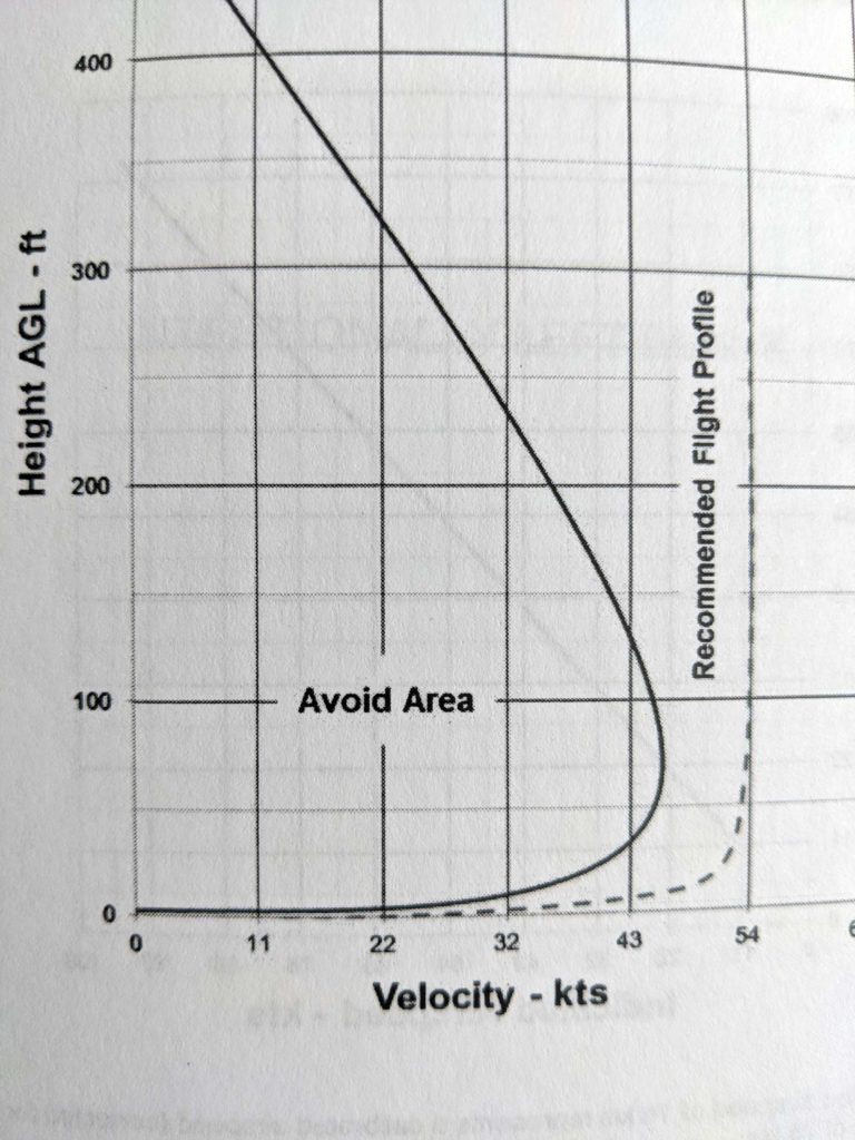
The Autogyro USA Cavalon Pilot Operating Handbook includes a “power curve” indicating safe operating airspeeds at various altitudes. Here’s what (most of it) looks like, at left.

Generally, this says that a speed of 55 kts or more is good at all elevations and that above 500 feet (where the full  curve meets the 0 kts vertical axis) all speeds are allowable. But during takeoff, we are at slow speeds and very low elevation. You’ll see that the curve visibly departs from the 0 altitude horizontal as low as 22 kts.

Thus normal operation anticipates becoming airborne before the airspeed needed for climbing is achieved. However the curve also limits operations to very low elevations—just 5 to 10 feet off the ground—until adequate speed has been achieved for a safe climb out.  The minimum speed for climb out is 45 kts with a recommended speed of 55 kts. Thus when we first become airborne, we fly just above the runway as we continue to build speed. Only once we have reached adequate speed is it safe to climb away from the runway. Of course, this usually happens very quickly as seen in this video. However, as the Pilot Handbook notes: 

“[O]peration ‘behind the power curve’ may have fatal consequences during take-off, initial climb or in any other situation with in ground proximity.”

  And now, finally, the video:

Saigon Foodie Scooter Tour

Saigon Scooter Foodie Tour

Today the Vietnamese government calls its biggest metropolis Ho Chi Minh City, but the historic name of “Saigon” still lingers. Visitors often remark on the traffic and the food. Recently I took a guided tour that combined both. At 6 o’clock one evening in May 2019, a young Vietnamese man who went by “Ben” (real name of Phuc) met me at my hotel and led me out to his Vespa to begin a freewheeling tour of favorite food spots around the city. This post covers the adventure with photos and links to the Google maps pins that I recorded at most of the locations.

Scooter Riding

Scooters swarm the roads of Saigon as the primary mode of transport for most folks. And while rules no doubt exist, the Vietnamese ride scooters the way Americans ride bicycles: any where and any way that they wish. When a stop light changes, riders from the formerly “green” direction continue to stream across the intersection even as riders from the new green direction start to ride through. This leads to some delays as the intersecting parties begin to meet and sort things out. But, in 10 or 15 seconds the sorting is done and the changeover has taken effect. That type of sorting process takes place all day and everywhere. No one ever assumes that they have a “right of way” as we do in the US. Riders take a “live-and-let-live” approach by accepting responsibility to look for and avoid other riders at all times. Rarely does anyone honk a horn in anger but often they do give out a quick “beep beep” that just means “I’m here, don’t hit me.”

The photos below were taken on my phone during the tour–and don’t miss the video! During my stay, I also shot pictures with my DSLR camera in order to document and study the scooter phenomenon. If you’d like to see the amazing sights and interesting portraits that emerged, take a look at that collection on raydaniels.com.

Scooter riders mingle with pedestrians in the market, riding right up to the stalls to order without getting off. (Although we were on foot!)
Ironically it is the kids who ride without helmets which are legally required. This is a common configuration with the youngest up front between the drivers arms and legs–often sitting on a small stool set in front of the seat!
My view for much of the evening.
Here’s a little taste of Saigon scooter traffic–just 20 seconds.

Food Cart Spring Rolls

First stop was at a food cart on a street corner. The item was typical Vietnamese spring roll: rice wrapper, shrimp, fresh Basil and lettuce. My guide paid and we were each handed one spring roll. But the guide said the reason for visiting this particular spring roll vendor was the sauce which he said the fellow made himself and which included several different kinds of beans. He was then handed a plastic cup half filled with a thick sauce the color of coffee. He asked if I was OK with some spice/heat and I said yes so a large glob of chili paste was added to the cup. We dipped and enjoyed.

Sit-Down Seafood

At our second stop, we visited something that more closely approximated a traditional restaurant and called Ốc Đào Quán. Mind you, it had no walls and nothing but a concrete slab for a floor, but the food was excellent! The first dish was octopus–or at least a part of the octopus! The dish contained what looked like little balls ranging in size from small peas to marbles. I was told these were octopus suckers! They were served in a tasty sauce that was slightly sweet and had a bit of chili heat. The meat itself was tender and the dish was fantastic–ultimately one of my favorites of the evening. We also had clams and scallops–both still in shell–and served with salt and a sauce. Oh, and a plate of mixed boiled seafood as well, I forgot about that until I saw the picture.

Octopus suckers! Looks like some other chunks of meat in there … I didn’t figure that part out. But boy was this good!

The Market

Once we’d gotten a good base down (honestly, I was full at this point and could have stopped there), we went to a street market and visited some of the vendors to try their wares. One was sausages (OK), another was rice pancakes (cool) and the third was a quail egg omelet (Oh, yeah that was good!)

By this point in the trip, Ben was directing me where to sit for photos and taking charge of my phone. You can see the vendor also enjoyed getting into this picture as I tend to the sausages on her charcoal brazier.

The rice pancakes were being sold packaged for people to take home, but the vendor would also toast one up for you to eat on the spot. Of course, Ben had a deal with them where the tourist handles the warming chore, so I was soon pressed into duty with Ben manning the phone. I pinned this here.

The finished, toasted rice pancakes were very crisp. One was savory with black sesame seeds, the other was sweet with bananas embedded in it.

The quail egg omelette was amazing. Two or three eggs cooked in a small clay dish on a brazier. As it cooked, they added various options–ours had some ham and something like cracklins added. At the end it gets dressed with basil and scallions and dosed with a white sauce that looked like mayo plus garlic/chili sauce. The result was fantastic!

By this point I’m pretty stuffed, but Ben wasn’t done! In truth we drove around a bit at this point, through another market and at one point turned down a narrow passage between two buildings quite similar to a Chicago-style gangway. (If we had met anyone going through someone would have had to reverse.) He toured me down a big nightlife street where the bars seats are set up like French cafes with rows of seats looking out at the street.

Final Stop

For our final stop, we went to a traditional style restaurant: on the second floor of a real building with walls, doors and even toilets! Here we had a snail sausage thing cooked inside the snail shell with a sprig of lemongrass wrapped around it to help you pull it out. Then a sort of crepe-textured omelette with mushroom inclusions that we then wrapped in various leaves to eat. I skipped the top leaves which looked fairly mundane and went for something with more character. Turned out it was a mustard leaf and packed a pretty good zing!

Snail sausage with lemongrass wrapped around it for easy retrieval.

Whew! That was a lot of food. But what a fun evening! I loved riding on the scooter and really enjoyed the food! I booked this trip (and a couple of others that I also enjoyed) through Private Daily Tours in Ho Chi Minh City (contacting them through WhatsApp) and I would highly recommend the experience.

Final picture: the view from my hotel room as the sun was rising the next morning. I felt great, though still full, and never had any ill effects from the adventure.

Christmas Stocking Stand

This was a “quick” project that arose from need: my wife saw a similar item in a catalog and decided to get a pair of them for a large family gathering this year (A total of 16 stockings will be hung.) Lo and behold the catalog items were already sold out. Enter handy husband. 

Total construction time (for two units) was 9 to 12 hours (measured in 3 hour sessions at the local welding shop, www.ciadc.org). Painting took a few more days as all the colors required multiple coats–and I started with a primer.  The welding was all MIG.

The one part of the design that’s not obvious from the general photo is that the legs detach near the top for storage. (See photos below.) The legs themselves are angle iron. To join the legs to the top, I created a bayonet-style joint. This consisted of a 1/4″ rod attached to the upper section and extending about 3 inches beyond it to slide into the leg sections. To create the receiving groove for the rod on the legs, I welded a flat piece of steel across the inside of the angle iron. The tricky part was getting that flat piece sized just right to make for a tight fit. 

Bayonet leg connection

Another small item is that there are feet on the bottom of the horizontal leg struts. These feet are just short sections of 1/2-inch diameter steel rod attached so that the curved side is against the floor. This gives the whole thing just four points of contact on the floor which will hopefully lead to less trouble with leveling, rocking, etc. (So far so good on the first installation.) Of course this can be handled in many different ways. Also: I capped the ends of the 1-inch square tubes on the base with plastic end caps. 

In the back-side photo you can see the attachment of the letters and the two rods that support them. You’ll also see the 1/4-inch rods attached to the angle iron for hanging the stockings to. The green S-hooks were also made for this project. I just wrapped some plastic coated heavy gauge wire around conduit to get those. 

Rear view. 

In the interests of time, I bought pre-cut steel letters and tack welded them in place. The letters are attached to two lengths of 1/8-inch rod attached at each side and running across the entire length of the piece. This worked very well. I wound up getting galvanized steel letters. Galvanized metal is NOT safe to weld due to the production of toxic fumes. I took the risk of doing it anyway, working under a large exhaust fan and going in for short sessions of tack welds before backing away to allow removal of all the fumes. If I had it to do over, I’d find letters that were not galvanized–or find some other way of attaching them.  

The entire piece was sandblasted after welding and grinding to prepare everything (and especially the galvanized letters) for painting. (Galvanized metal doesn’t take paint well at all.)


Building Kitchen Stools

In 2017, we rehabbed our kitchen and installed a large island with a counter-height sitting and eating area. We had some bar stools, but they were “bar” height–too tall for the new counter.

In the process of looking for stools, I eventually decided that I could build something that we would like as well or better than what we saw on sale. And so I did.

The whole process from idea to finished stools took more than four months–although part of that was due to neglect on some of the final steps.

First I Needed a Design

With the help of Pinterest I collected stools that I liked and started to develop two types of criteria. First: what we wanted for our kitchen. Second: what I needed to be able to build an attractive and useable stool.

I found a stool that we liked which was offered commercially in wood and with some differences in back and seat from what we wanted. Using that as a model for the basic dimensions and angles, I put together drawings and started to work out detailed specs for each piece.

Planning to Build

Once I had the design, I started to think about how to build four stools that would all look the same. I had honed my skills in measuring and cutting metal tube consistently on a previous furniture project where I made two matching end tables. But all those angles had been 90°! For this project I had pieces with various shallow angle cuts from 4.5° to 13° and few of the connections between pieces would be square . For the angled back support, I had two measured cuts abutting each other, so if either was wrong on any one of the stools, you’d notice when the four finished stools were lined up next to each other at the counter.

Next I realized that I’d need a way to hold the pieces in place while I joined them with welds. The normal clamps and magnets used for 90° corners weren’t going to cut it. So the first thing I had to build was a jig that I could anchor all the parts to before I started. And of course the jig had to get all the angles right as well. So that took more design. Building the jig took about 9 hours (three sessions at ciadc.com). It consists of steel angle iron stock with blocks of tubing attached as “stops” for the stool pieces. All of this was MIG welded.

Prototype

Prototype stool after welding. After lots of planning and visualization, this was the first time I had something real to look at.

Once the jig was done, I cut all the pieces for one stool and started to fit them together. In the process, I found one error in my calculations. Fortunately it required a piece to be shorter than I had planned, so it was an easy fix.

Then I built the first stool, using a TIG welder. Once I finished all the welds for this first stool, I realized there was one aspect of the design I hadn’t closely examined. With everything welded together, I wasn’t sure that I’d be able to separate the finished stool from the jig!  Fortunately, it popped free with just a little elbow grease.  The photo at right shows the prototype fresh off the jig. You can still see the rough welds.

Once I had this prototype frame, I cut potential seat designs from 3/4″

Completed and useable prototype.

plywood. One was a simple circle, but the one I liked better was a larger circle squared off at the front. While the model chair I’d seen online used a short, wide rectangle for the back, I was more interested in carrying the curve of the seat into the back rest as well.  I hit on the idea of using a small section of a circle. While the size is not exactly the same, the seat and back look like they could form a complete circle when put together.  With these attached, I had a final prototype that we could actually sit in and use for a few days to ensure that it would meet our needs.

Building

With all the design elements and measurements confirmed and the construction process established, I was ready to build additional stools so that we would have four matching pieces when finished. This build process took the better part of a full work week which I accomplished during an “Intensive” class at the same shop where I did all the metal and woodworking work: the Chicago Industrial Arts and Design Arts Center (ciadc.org).

I focused closely on making each stool identical to the others. Along the way, I wound up remaking two of the 24 total pieces. One was because the original piece was too different from the others it was supposed to match. One was because I did a poor job aligning the pieces properly during welding and got the back rest angle wrong. In any case, all 24 pieces were cut, attached to the jig, welded, ground smooth and wire brushed to ready them for painting by the end of the week.

Finishing

This is a finished stool after powder coating. Between grinding and finishing, the welds have virtually disappeared.

While wire-brushed steel has a certain attraction, it wasn’t quite what I was looking for. And my wife–having sat on the wood seat of the prototype for a few days–was interested in upholstered (and padded) seats.  To get these things done, I called on the expertise of outside organizations for powder

coating the frames and then upholstering the wood forms I made for the seats. (Note:  powder coating is basically painting that uses electricity to attract the paint/pigment to the metal and then bakes it on for a durable finish.) Both turned out really well, I think and resulted in finished stools that we are very happy with.